Experimental facilities
The Fluminance team has several wind tunnels located in the IRSTEA centre in Rennes. Two of them are large facilities dedicated to the study of low to medium speed air flows encountered in industrial and environmental situations where local shear stresses – typically steep velocity gradients induced by winds, blowers, air curtains, etc. – produce complex mixing phenomena.
Turbulent anisothermal mixing layer

This wind tunnel is fifteen meters long. It is dedicated to the study of plane mixing layers where two parallel flows with different velocities and temperature give rise to a turbulent mixing. The wind tunnel is allowed to rotate around its longitudinal axis to separate the effects of forced convection from natural gravity effects in mixed convection studies.The two parallel and horizontal streams with different velocities and temperatures are generated through separated plenum chambers and convergent tunels. They merge and initiate a mixing process behind the 2 meter long thin horizontal trailing edge and tapering separating plate. The mixing is induced by the combination of the turbulent mixing due to the local shear between the two streams and of the natural convection between the upper and lower flows at different temperatures. The 3 meter long test section has a cross section of 1 × 1 m2. Transparent walls are used to allow optical measurements. The bulk velocities of the lower (U1) and upper (U2) flows can be fixed separately in the range [1 m/s, 5 m/s]. The temperatures T1 (lower flow) and T2 (upper flow) may vary in the range [5°, 35° ]. This wind tunnel aims at analyzing the reciprocal influences of the velocity and temperature gradients in the mixing process.
The magnitudes of the inlet velocity and temperature gradients cover a large Richardson number range, which measures the ratio between buoyancy and inertial forces, and the coefficient λ = (U1-U2)/(U1+U2) that classically determines the expansion rate of the mixing layer in isothermal conditions.
Turbulent anisothermal planar jet in co-flowing stream

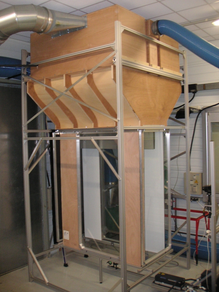
The planar-jet blowing equipment is 5 m high and takes up 2 × 2 m2 on the ground. A metallic structure hold vertically 1 central and 2 adjacent open-circuit air wind tunnels. The 3 wind tunnels are independent, juxtaposed and blow down. For the central wind tunnel, a variable-speed centrifugal fan supplies with air the planar jet through a plenum chamber (section of 200 × 20 cm2) with filter foams, honey comb and grid following by a symmetric convergent tunnel with a factor of 4. The planar jet at the entrance of the testing zone is then 5 cm thick and 2 m span given an aspect ratio of 40. For each adjacent wind tunnel, a variable-speed centrifugal fan supplies the plenum chamber (section of 200 × 80 cm2) made up as previously and following by a dissymmetric convergent with a factor of 8/3 (given a section of 200 × 30 cm2 at the entrance of the testing zone). The turbulent planar jet and the two adjacent co-flowing parallel air stream exhaust into the vertical testing zone. The 2 m long testing zone has a cross section of 200 × 65 m2. The transparent walls on two opposite sides allow optical measurements. The screens on two other sides avoid confinement effect on the planar jet development. The air stream leaves the testing zone by a clearance of 50 cm between the ground and the exit of the testing zone. The flow velocity can be chosen continuously between 0.5 m/s and 9 m/s for the planar jet and between 0.5 m/s and 3.5 m/s for the co-flowing stream. The free stream turbulence intensity is less than 0.5 %. The temperature is kept within 0.2° by using air-water heat exchanger.
The turbulent planar jet is a simple and useful model for many applications such as air curtain devices. The added of a parallel co-flowing stream to the jet has numerous advantages:
- There are no more still and reverse flow in the outer region of the jet and hot-wire anemometry can be used;
- The outer flow can be properly seeded with particles so that better conditions are obtained for Particle Image Velocimetry or Laser Doppler Anemometry experiments;
- External conditions to the jet can be easily controlled such as temperature and flow disturbance;
- Numerical studies add generally a low co-flowing stream to the inlet condition for more convenient reasons.
Particle Image Velocimetry (PIV) systems
Fluminance has 2 PIV systems. The first one is a Stereoscopic PIV system with a NewWave laser Solo 3 Nd-YAG (pulse energy of 2 × 50 mJ at 15 Hz) and 2 PCO cameras SensiCam (CCD size of 1280 × 1024 px). This system allows the measurement of instantaneous velocity vector fields in a plane of turbulent flow. The second one is a Time-Resolved PIV system with NewWave laser Pegasus (pulse energy of 2 × 10 mJ at 3 kHz) and 1 camera APX-RS (1024 × 1024 px at 1-3 kHz). This system is fast enough to follow the time evolution of flow but only the 2 in-plane components of the velocity vectors are measured.


